Overview
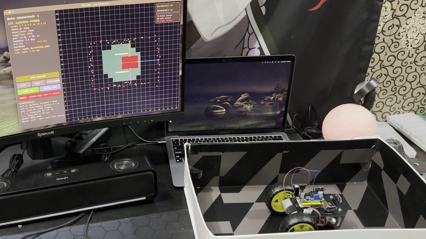
Nanodot is a small, stepper-driven robot that starts from a known origin, measures the space around it with time-of-flight distance sensors, and builds a map of its surroundings as it drives. A Python simulator on the laptop mirrors the physical bot in real time, drawing its actual position and live sensor readings, and turns every sensor hit into a growing point-cloud map. The long-term goal is a three-bot swarm doing proper SLAM; this build gets one bot working end to end first.
How it fits together
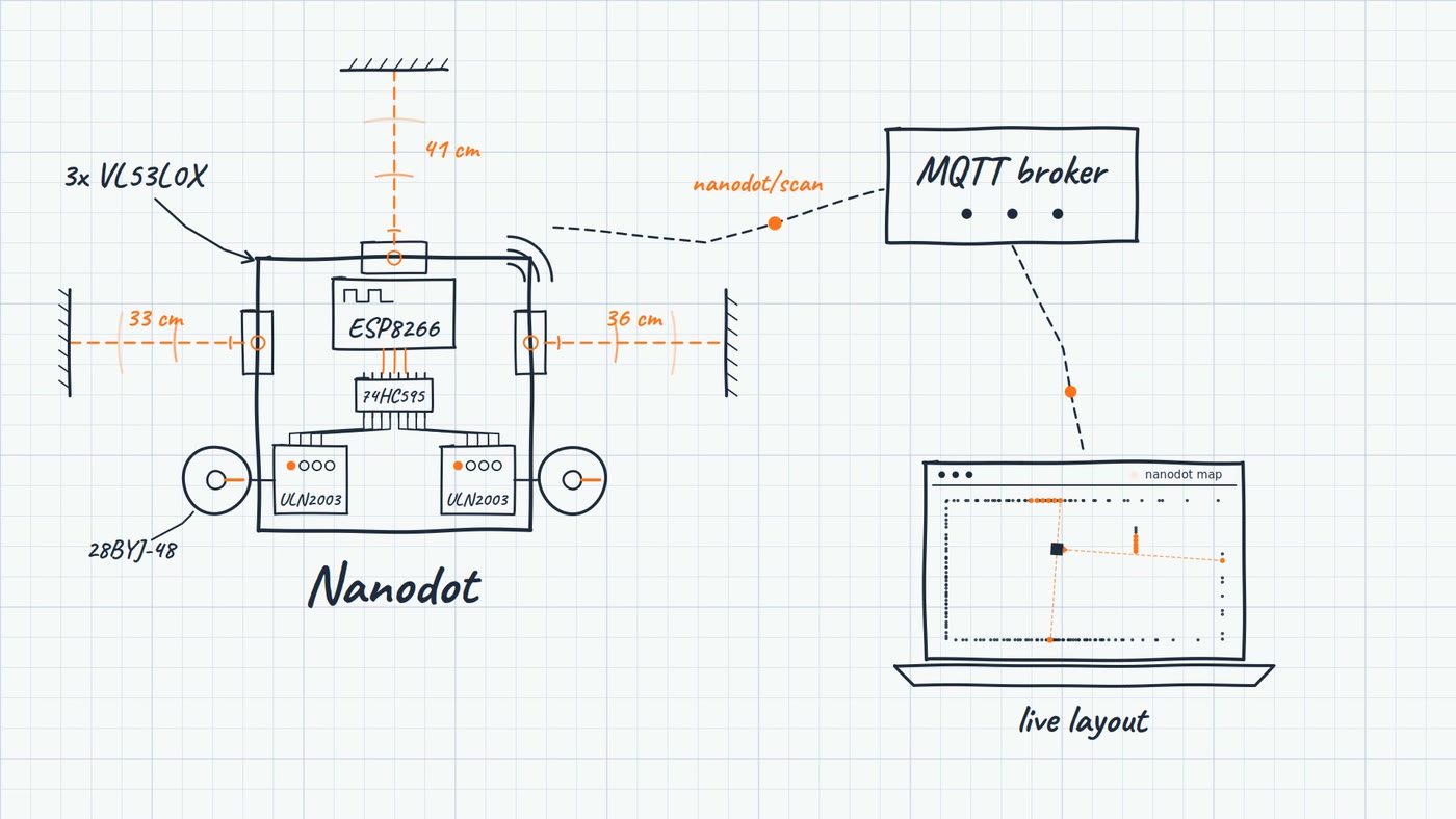
The ESP8266 reads three distance sensors, drives two steppers, and publishes its pose and readings to an MQTT broker. The simulator subscribes to the same topic, draws the bot and its map, and sends drive commands back from the keyboard.
Hardware
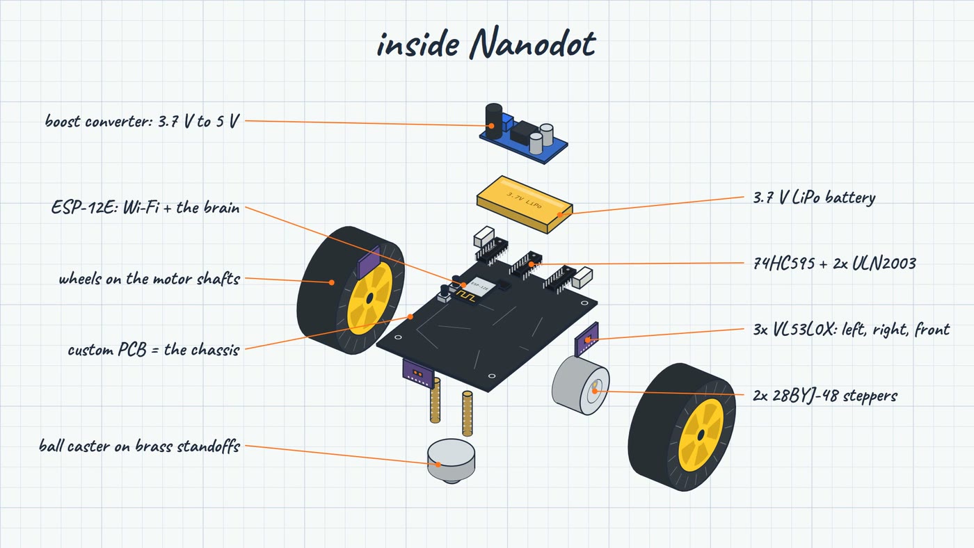
- Brain: ESP8266 (ESP-12E), prototyped on a NodeMCU and moved to a bare module for the final board.
- Drive: two 28BYJ-48 steppers through ULN2003 drivers.
- Sensing: three VL53L0X time-of-flight sensors on one I2C bus, each given its own address at boot by bringing them up one at a time with their XSHUT pins.
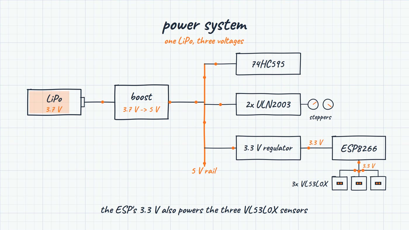
- Power: a 3.7V 1000mAh Li-ion cell, boosted to 5V for the motors and regulated down to 3.3V for the logic.
Why steppers
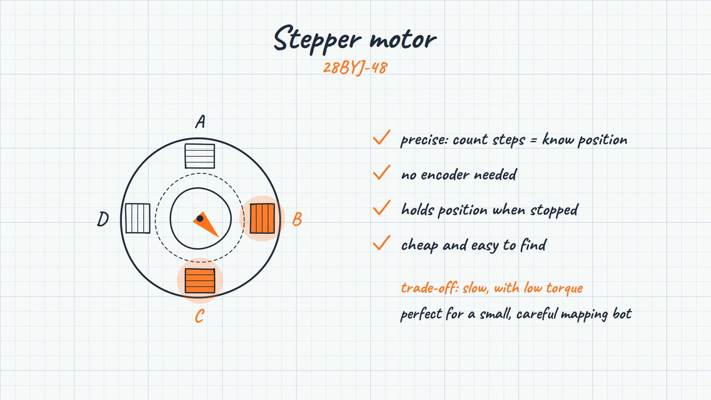
Continuous-rotation servos were ruled out because they give no position feedback. DC gear motors with encoders (GA25-370, N20 and TT motors on a TB6612FNG H-bridge) were the serious option, until a suitable 5V geared motor with an encoder couldn't be found locally in Pakistan. Steppers made the problem go away: every step is a known angle, so wheel travel, and from it the bot's position, comes straight from the step count with no encoder at all.
Three pins, eight coils
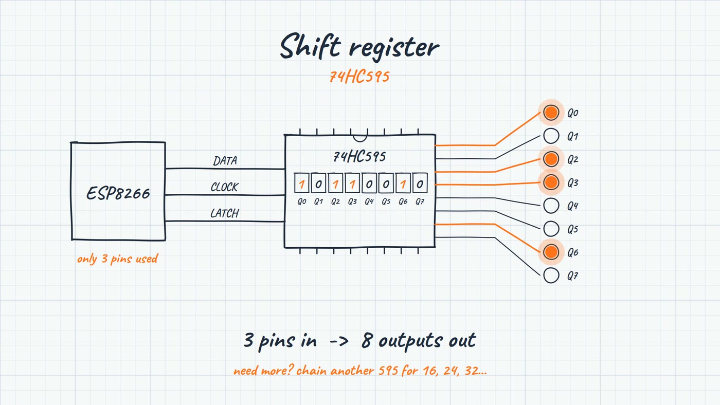
Two steppers need eight coil lines, and the ESP8266 doesn't have many GPIO pins to spare once the sensors are wired up. A 74HC595 shift register takes data, clock and latch from the ESP and fans them out to all eight coils.
Power
Custom PCB
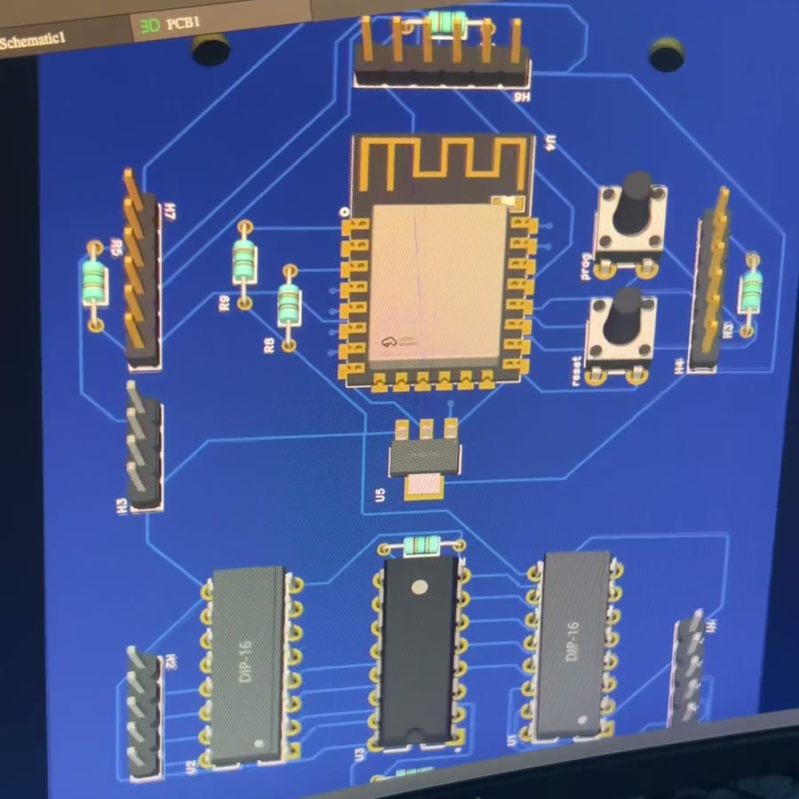
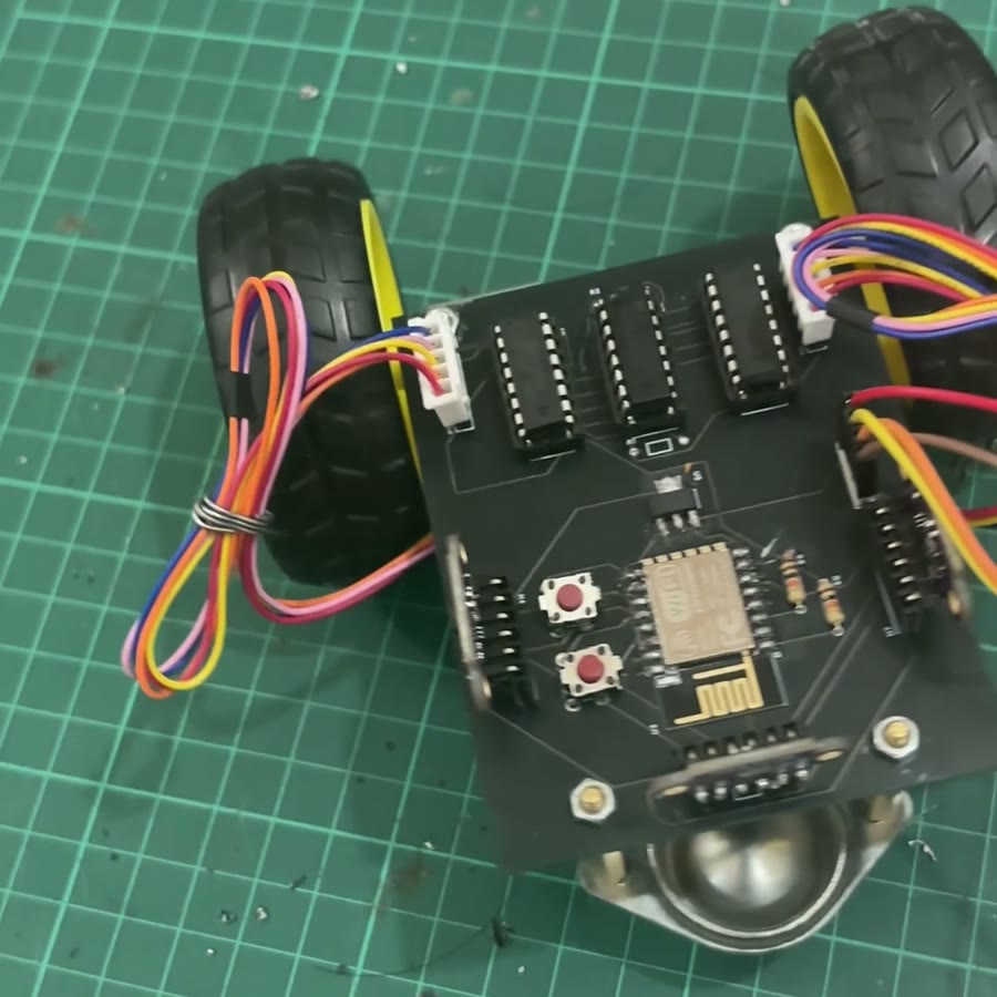
The final board is designed in-house at 68 × 87 mm. It carries the ESP-12E, shift register, both motor drivers, and the sensor headers, and the motors and ball caster bolt straight onto it, so the PCB is the chassis too.
Firmware and protocol
- No hardcoded WiFi: on first boot the bot opens its own setup access point (WiFiManager) to collect credentials.
- Odometry: differential-drive position computed exactly from step counts and measured wheel geometry.
- Exact 90° turns: step counts worked out from the real chassis geometry, not tuned by trial and error.
- Hard stop: a stop command skips the move queue and interrupts a move in progress.
- Sensor recovery: a failed read is retried once automatically before it's reported as an error.
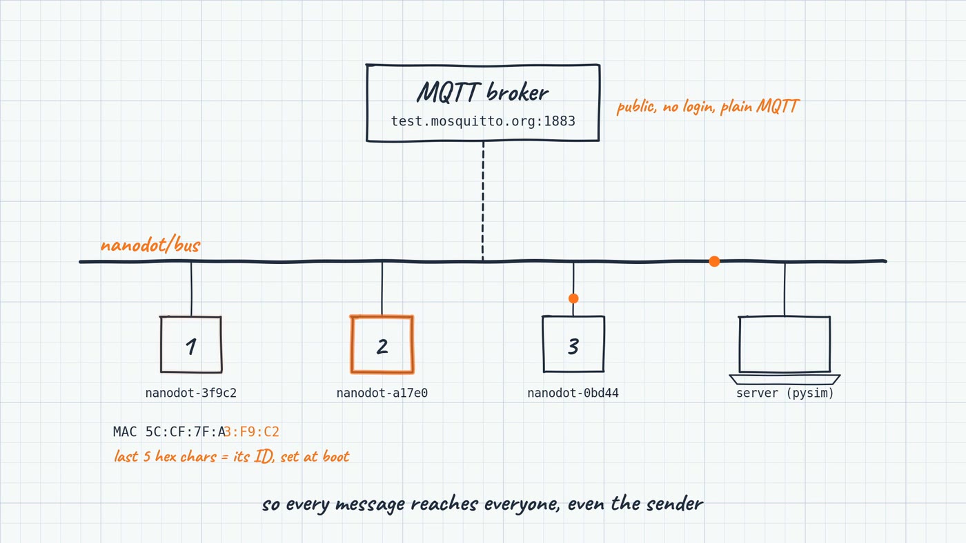
Every bot and the server share one topic, nanodot/bus, on the public
Mosquitto test broker. Messages use one JSON envelope (sender, receiver, type, data)
for handshake, heartbeat, motion and command messages, and each bot keeps only the
messages addressed to its ID or to everyone. Adding the second and third bot needs no
protocol changes.
Live simulation
The Pygame simulator draws the bot at its real position with its three live sensor rays, accumulates every hit into a point-cloud map of the actual room, and lets you drive the bot from the keyboard over MQTT.
Bugs along the way
- A sensor's XSHUT line on an ESP8266 boot-strapping pin kept the chip from booting. The cause was the breakout's own onboard pull-up fighting the boot requirement, fixed by removing that resistor.
- Motor flicker traced first to a non-latching 74HC164 mistaken for the 74HC595, then to a cold solder joint on the latch pin.
- A 3.3V/5V logic-level mismatch caused intermittent behaviour.
- SDA and SCL were wired the wrong way round, which silently killed I2C until a raw register-read test found it.
- Drive forward and turn were swapped because the two motors are mounted mirrored on the chassis, fixed with a single isolated compensation constant.
What's next
- Message acknowledgement and retry over MQTT.
- Battery voltage monitoring.
- Scaling from one bot to the full three-bot swarm.
- Open-sourcing the code and PCB design, and sending spare boards to students and makers who want to build their own.